
WHY CONSIDER IMPROVEMENTS
Although I seem to have gained a reputation for being somewhat of a Healey modifier I still believe strongly that a standard Healey in good mechanical condition is a fine car to drive and preserve, and I only offer what follows in response to several enquiries that I have had on the subject. I do not consider myself to be an expert, but I have some experience and what follows is based upon that; furthermore I’m sure that most of what I’m going to say will be obvious to those who have considered the subject in any depth but, for those who haven’t, this should be a good starting point .
Because the big Healey is the epitome of a “sports car” it is not unreasonable to think that perhaps it should handle in a sporting like manner. It is pretty disappointing to take your car out to a friendly gymkhana or similar event and find that no matter how well you drive 1200c.c. rice rockets are completing the course in half the time it takes you and your Healey. What I’m describing below should result in some respectable improvements and is, for the most part, easily reversible; I’m not advocating modifying the car so dramatically that it looses its classic appeal.
SOME BACKGROUND
Up until 1965 all big Healey’s used the same suspension which dates from 1952. Many of the components were probably designed for a cars built immediately after WWII. The rear suspension of the big Healey is an interesting study in design compromises. In the interests of styling and to minimize manufacturing costs Donald Healey opted to use a rather outdated “under slung” ladder frame for the 100. I’m pretty sure that the Healey was the last mass produced car to use this design. One of the most demanding compromises which has to be addressed with this type of design is the spread of the main frame rails. Positioning the frame rails far apart improves the rigidity of the frame but places some major limitations on the suspension. With the Healey I believe the spread of the frame rails was determined by the front suspension and that the rear was built around the result.

UNDERSLUNG FRAME
The problem with the under slung design is that the available suspension travel is limited by a factor of the distance from the underside of the rear axle to the ground. In the case of a Healey the total travel available is less than 12 cm. Common practice in suspension design is to maintain the car’s normal ride height at or slightly above about mid travel. This means that the axle has only about 6 cm of available movement either up or down, and that is not very much. If you watch the suspension of a car driving next to you some time, you will see that an average car uses 10-15 cm of travel along a relatively smooth piece of highway.
The Healey design did produce a “firm” ride but, for cross ply tyres, which were all that was available in those days, the suspension was reasonably adequate.
HEALEY SUSPENSION IN THE 21ST CENTURY
Radial ply tyres became commonly available in the early 1960s and their improved grip means that they can generate forces in suspension systems that are substantially higher than could be generated with the bias or cross ply tyres. As a result, with good tyres and some not very aggressive driving, the body roll of a Healey can be quite significant. Body roll in itself is not necessarily a bad thing, but it can have some negative effects when it causes excessive changes in camber of the wheels. i.e. their inclination relative to the ground.
However in the case of a Healey with its under slung frame, there is another major problem in that the body roll can be so significant that the rear frame on the inside of the turn rises sufficiently to contact the axle, which in turn lifts the inside tyre off the ground.

WHEEL LIFT
This has two immediate effects. Firstly the inside wheel spins because it cannot transfer the engine power to the ground and secondly the back of the car tends to step sideways. This sideways stepping is because tyres, particularly radial ply tyres in motion, behave a little oddly. Explained in simple terms, two tyres carrying 500 pounds each will have considerably greater resistance to side thrusts that one tyre carrying 250 pounds and the other carrying 750 pounds or in other words lift off one rear wheel and because the load on the rear tyres is suddenly transferred completely to the outside tyre things go very pear shaped indeed.
THE FIX
To rectify this situation we have several options.
1. We could fit stiffer springs. The problem is this would result in an even harsher ride, possibly okay for a smooth race track but definitely not ideal for street use.
2. We could increase the available space for rear axle travel. This is the solution that B.M.C. adopted in 1965, but it required some fairly extensive frame modifications which are out of the question for most people.
3. We could add roll stiffness to decrease the amount of body roll in turns and this is the course we will pursue here.
INCREASING ROLL STIFFNESS
Roll stiffness can be easily increased by installing anti roll bars. The front of a Healey already has an anti roll bar and you can stiffen this a little by eliminating the softness of the bushes or considerably more by fitting a thicker bar. Increasing the front roll stiffness results in the outside front wheel supporting more weight in the turn and the car staying more level however, as a result of the uneven tyre loading thing mentioned above, this change alone will produce massive understeer. Understeer, for those not familiar with the term, means you turn the steering wheel but the car to a greater or lesser degree carries on straight ahead.
To achieve the desired result roll stiffness has to be increased both front and rear, and then balanced between ends to keep the tyre weights where you want them through the turn. When this is done correctly the weight transfer in the turn will be evenly distributed between the front and rear wheels and this will produce the maximum grip.
SOME THINGS TO CONSIDER
1) Increasing roll stiffness will have a detrimental effect on the way the car negotiates one side bumps but a further modification; fitting tube shocks will improve this dramatically.
2) Installing most of the available rear anti roll bar kits involves welding to the frame.
(I have developed a design for a rear anti roll bar which requires only the drilling of 4 holes for installation but as yet I have not had an opportunity to test the design).
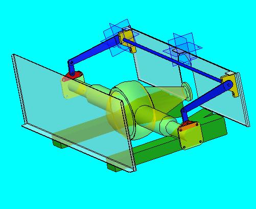
REAR ANTI ROLL BAR SYSTEM UNDER DEVELOPMENT
3) When it comes time to make adjustments remember; the stiffness of an anti roll bar increases as the fourth power of its diameter so a very slightly thicker bar will be substantially stiffer.
I hope that all helps.
Hi – I’m interested in trying some of the mods you talk about (fascinating stuff..) but wanted first to check my car’s ride height is about right. it’s a BN4. Since body panels are unreliable as datums, can you tell me what ought to be the clearance between the bottom of the axle casing and the top of the chassis members (all components in new condition)? thanks John
Michael,
How timely to read about roll bars to improve healey handling. Today, 1/30/07, I transported my MKII to a welding shop for a little work. As I have always told people I am restoring my 3000 to the best of 1940’s and 1950’s technology. I am very interested in doing it better without compromising correctness. Hopefully you will have your anti-roll kit available within a year or so. Do you need a tester and test car? BTW, I always enjoy your posts on the healey list.
john
Thanks for your comments Steve; I really lke your idea of usinga pair of modified exhaust clamps. When I get back to this project I will certainly see if that is an easier solution.
Hi Mike,
I’m interested in your anti-roll bar design. Hopefully it will work out in the front of the compartment as shown. In my own case, I’ve got a Cape tube shock setup that takes up the space in the upper rear corner all the way across.
FWIW–regarding the axle mounts, a couple of comments based on observations I just made on my BN6 with BJ8-style radius arms.
It appears using the bolts from the axle flange for the lower brackets is problematic because they’re too far outboard and the linkage would be on the outboard side of the bump boxes. If I may be so bold as to suggest alternatives:
Consider these two ways to do the axle brackets: the BJ8 way and the non-BJ8 way.
For the BJ8, you could run a longer 7/16″ bolt through the radius arm bracket, with a spacer and use a rose jointed uplink from there. Pegasus now sells teflon-lined rose joints.
For non-BJ8s you might consider a bracket made from a 2-1/2″ heavy-duty muffler clamp with a vertical tab welded to the cross-piece with a 7/16″ hole for a mounting bolt for the uplink. This would clamp around the axle just inboard of the leaf spring. I just emailed you a sketch.
For the upper mounts, surely the sheet metal there is no less strong than the slim uprights used on AHX-12. It would be convenient if the upper mounts used commonly-available poly bushings
From my own selfish point of view, I hope the bar is available in a thickness compatible with a 3/4″ front bar not just with a 7/8″ front bar.
Michael, thanks for the information on Healey chassis and handling, as I look at the ways to improve the car without completely changing the character of the car too much this kind of thing is very useful. While I have not had extensive competition experience I have autocrossed my 100 at local club events, though I do get beat by some of the more nimble small bore stuff, I have managed to hold off the TR6s that run in the same class.
Would add that the Triumph TR4A, in optional American solid axle form, retained an underslung axle until its demise in ’67. I can also attest that it exhibited all of the handling shortcomings you outline for an underslung design.
Michael:
Exactly what you propose has been done with a friend’s 3000 that he’s having modified as a rally car by one of the UK’s better known Healey shops.
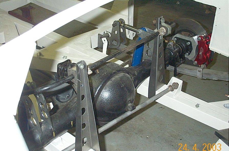
The rear anti-sway bar is a standard one as supplied by Denis Welch but instead of mounting it as usual to the underside of the chassis rails it is to be mounted as you suggest, above the driveshaft.
Rather than mount it directly to the sheet metal panels there are two iron uprights approximately two inches wide and an inch + deep and run from the bottom of the rear seat panel (to which they’re welded) down the rear panels (also welded) to the bottom of the chassis rails to which they’re also welded. I don’t know how thick they are but presume its pretty substantial.
As I recall, the mounts to the rear axle are as DW instructs- welded to the rear center-line to match the width of the anti-sway bar.
I believe the axle mounts were positioned first, then the sway bar put in place as desired above, with its chassis mounts then used to determine the position and depth of the uprights to which i=they were then mounted.
A photo:
http://healeyjournal.tripod.com/images/rearswaybartopmount.jpg
which shows the chassis mounts and bushings in position on the uprights without the bar itself yet positioned.
I trust this helps.
James
Hi Ken,
I have always admired Geoff’s wisdom, particularly after he helped me resolve a detonation problem I had with the “S at Mid Ohio, and I would very much like to know what the rational was behind that statement.
When I first installed a heavy ARB on the front my “S” the understeer was unbelievably bad. I almost put the car through a fence on the first turn of the first test drive. When I then added a back bar I encountered the problems that you did with oversteer. It was only after adjusting things several times and finally ending up with a very light rear bar with long arms did the handling start to work.
I have never used Traction Masters but I could definitely see that they would help improve things on a Healey. When a pre ’65 Healey is leaning into a turn the frame gets really close to the underside of the axle. I could believe that the Hotchkis type drive of the Healey produces a slight anti squat property which, when power is applied in a turn, lifts the frame a little and could make the chassis contact the axle.
Do you have any photos of the Huffaker setup?
Michael,
How do you reconcile the addition of a rear sway bar to Geoff’s comments to me that it was a dumb idea? I think ‘heavens no’ were his exact words. I didn’t question why or ask about theory, because when I was slaloming with one, it really made the car spin. I already had a thicker front bar. So I thought he was confirming my experiences. I did think that it felt good on freeway banked ramps. I still have the ADDCO bar which mounted to the frame stored away.
The early Huffaker Healey 3000 rear swaybar set up is like yours, mounted to the sheetmetal high above the frame. It also used Traction Masters.
Ken