
Judy and I were lucky enough to be able to participate in the Austin Healey Car Club of New Zealand’s 50th anniversary tour in February 2023. This was a fabulous “once in a lifetime” experience for us.
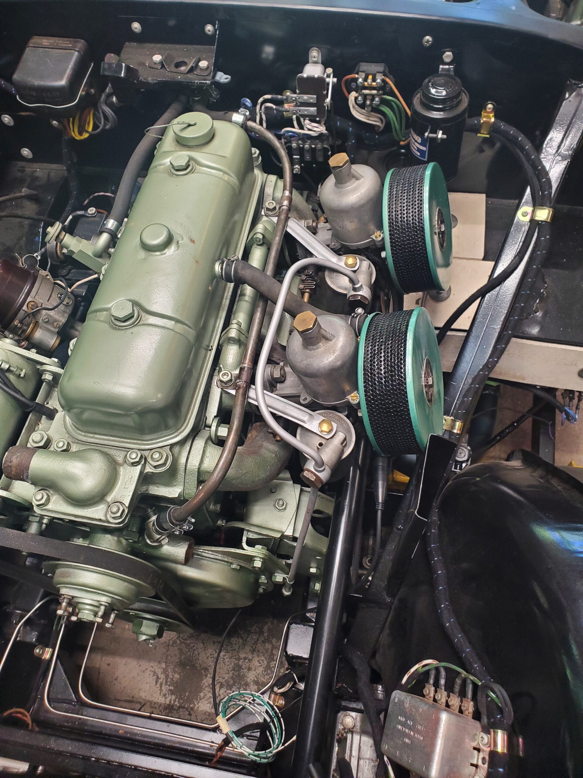
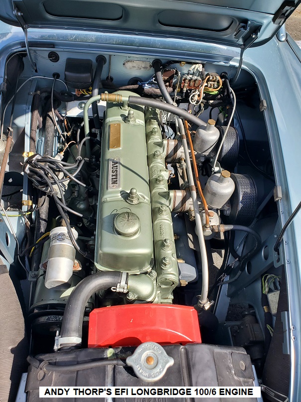
Because of the turmoil in the international shipping industry as a result of covid shipping my 100 to New Zealand for the event turned out to be impossible however Andy Thorpe from Auckland was kind enough to lend us his fabulous, fuel injected, Longbridge 100/6 for the entire tour.

I had heard about this car and was really looking forward to driving it as I have always felt that electronic fuel injection (EFI), if done properly, could be a great improvement to a Healey and would solve all the drivability issues attributable to using currently available pump fuel in ancient carburetted cars.
Andy’s car is a work of art. He has managed to install a completely reliable EFI system in such a manner that it is almost impossible to see and, as a result of his work, the car drives better than any Healey I have ever driven.
After this experience I decided that I wanted to do the same to the BN2 that I am restoring however, in hindsight, this may have been something of a rash decision as I really had no idea of just how much work this conversion would entail.

THE PLAN
The automotive carburettor is actually a fairly amazing device which, with the benefit of only one “analog” input, manages to deliver approximately the correct amount of fuel to an engine with incredible reliability. An electronic fuel injection system certainly does a much better job of metering the fuel input but requires a mind-boggling array of “digital” inputs and electronics to achieve essentially the same thing. These inputs include the following.
- Engine RPM & Crankshaft position
- Camshaft position
- Coolant temperature
- Intake air temperature
- Intake manifold pressure
- Exhaust gas oxygen content
- Throttle position
- Fuel pressure
All this information has to be fed into a small computer (ECU) which, after a considerable amount of setup, sends appropriate signals to injectors to deliver the required amount of fuel.
Of course, there wasn’t a lot of consideration given to just how all these inputs would be measured when the 100 engine was developed sometime in the 1940’s so making the necessary modification to acquire this “data” and then install injectors to deliver the fuel presents a considerable challenge.
Fortunately, I was starting this process at exactly the correct point in this car’s restoration. The car has only 28 thousand miles on it from new and I had gone over the engine and gearbox very carefully but had yet to reinstall them
FUEL PUMP & LINES
After digesting just how big of an undertaking this was going to be I decided that I would start by installing the necessary fuel delivery system i.e., the fuel pump and lines. The type of injection system that I intend to install requires a fuel delivery pressure of 3 BAR (approximately 45 p.s.i.) and there was no way that could be achieved with the original SU pump.
It turns out that one of the complications of delivering this pressure is that the fuel pump absorbs quite a bit of electrical energy and in so doing gets quite warm. As a result, unless the pump is cooled continuously, fuel arriving at the inlet of the pump tends to boil and, as the pump will not pump vapour, it stops delivering fuel. After discussing this issue at length with Andy I decided that the best solution would be to do what almost every current manufacturer does and install the pump inside the fuel tank.
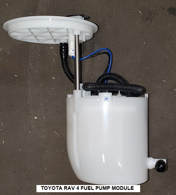
After searching around for a pump small enough to fit inside a Healey fuel tank I settled on one from a Toyota RAV4. I decided to use the complete fuel pump “module” which includes the pump, a “well” within which the pump resides, and intake filter and a fuel pressure relief valve.
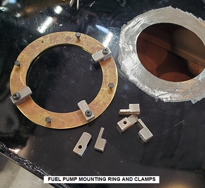
Getting this secured inside the Healey tank required that I cut a large hole in exactly the correct position to locate the pump in the deepest part of the tank then make a large ring to be soldered to the tank through which the module is inserted and secured by eight handmade clamps.
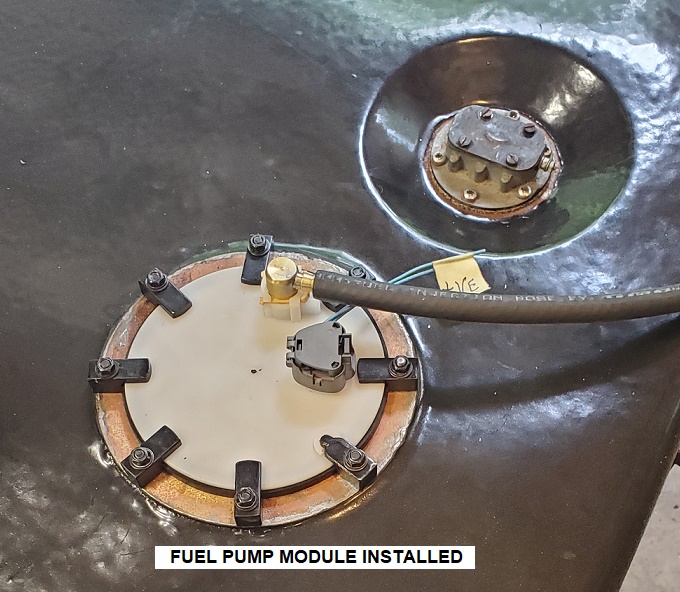
As a result of this the fuel delivery line was positioned nowhere near the original position on the 100 but this issue that was overcome by cutting a new hole which will be hidden by the boot lining mat.
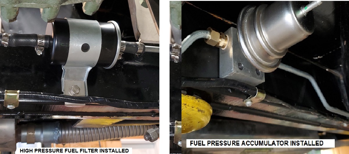
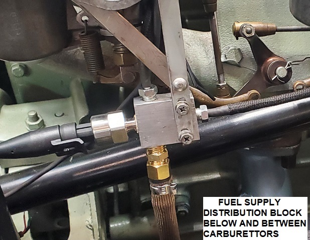
After passing through the boot front wall the fuel line, containing fuel at 3 BAR, is routed along the frame rail to a fuel pressure accumulator, a high pressure filter and then to a distribution block mounted below the front carburettor. The distribution block contains a fuel pressure sensor and has 2 outlets which direct fuel to the injectors.
EVAPORATIVE LOSS SYSTEM
The heat from the pump’s operation of course tends to heat the fuel in the tank which in turn results in the fuel producing much more vapour than would be the case with the SU pump. Originally these vapours vent through the filler cap into the boot given the much larger volume this would not be acceptable.
This vapour problem has been resolved by installing another emission control called “evaporative emission control system” or EVAP. To achieve this the pickup tube which is normally inside the Healey tank at the fuel outlet was removed allowing the fuel vapours to be drawn from the tank through what was originally the fuel line connection. This line was then run to a charcoal canister mounted next to the original SU fuel pump.
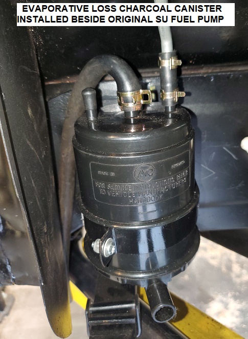
A “purge” line was then run from the charcoal canister along the inside of the inner sill to an evaporative loss “purge” valve and another line from the purge valve connects to the rear air filter housing inboard of the air filter itself.
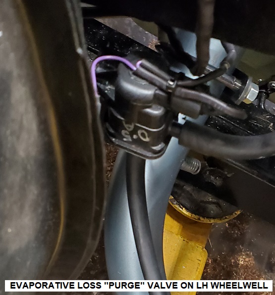
The idea is that whilst the car is not running the purge valve is closed and vapours generated in the tank pass through the charcoal, which removes the fuel vapour content, and then to atmosphere through the bottom of the canister. When the engine is started the purge valve, which is controlled by the ECU, opens allowing air to enter the bottom of the charcoal canister, pass through the charcoal, absorbing the fuel content as it does, then along the tube to the purge valve and then is drawn into the engine. I’m fairly confident that the slightly lower than atmospheric pressure at the mouth of the carburettor will be sufficient to draw the purge air through the system.
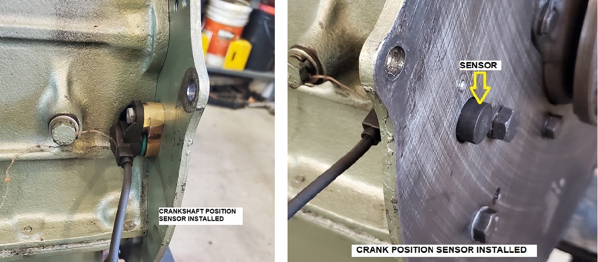
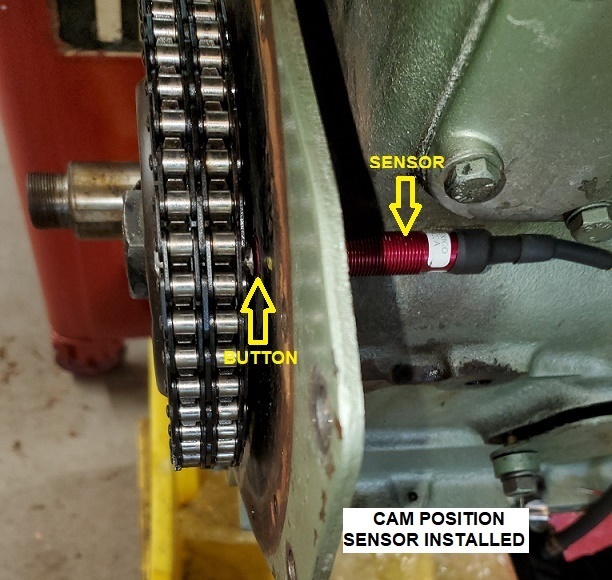
CRANK AND CAM POSITION SENSORS
The next task was to fit the engine with its crank and cam position sensors. The crank sensor is from a BMW and is mounted through the engine back plate where it protrudes sufficiently to detect the extended ends of special clutch pressure plate securing screws. For the cam a small “button” is mounted through the camshaft sprocket which is detected by the cam sensor which protrudes through the engine front plate under the left engine mount.
MAP SENSOR
With that completed I turned my attention to the manifold absolute pressure (MAP) sensor. This sensor measures intake manifold vacuum but, on a 2-carburettor engine getting an accurate and stable vacuum source is quite difficult. My solution is very “experimental” but the best I could come up with for this engine. I constructed a small “plenum” chamber from a piece of copper drain pipe which is connected to the fuel drain nipples on the underside of each inlet manifold. A small capillary line is installed on the underside of the plenum to allow any fuel which may accumulate within it to drain out when the engine isn’t running.
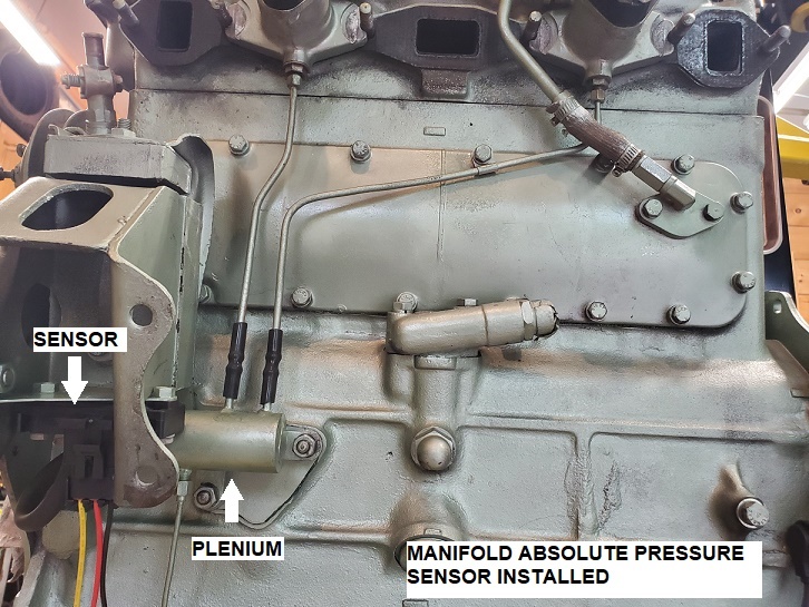
My calculations as to the volume of the plenum and the size of the two vacuum tubes is very much a guess, we will have to see how it works out. A fourth connection from the plenum has a tube running to the MAP sensor itself which is mounted on a bracket on the underside of the left engine mount.
INTAKE AIR SENSOR
The ECU (engine control unit) adjusts or “trims” the fuel delivery to compensate for changes in the temperature of the air entering the engine. This is achieved by using a temperature sensitive resistor or “thermistor” exposed to the air stream entering the intake. These tiny devices are rather fragile so I constructed a perforated tube from a piece of fuel line and inserted it through the atmospheric pressure inlet hole in the front carburettor body in such a way that the thermistor was situated inside the air filter housing.
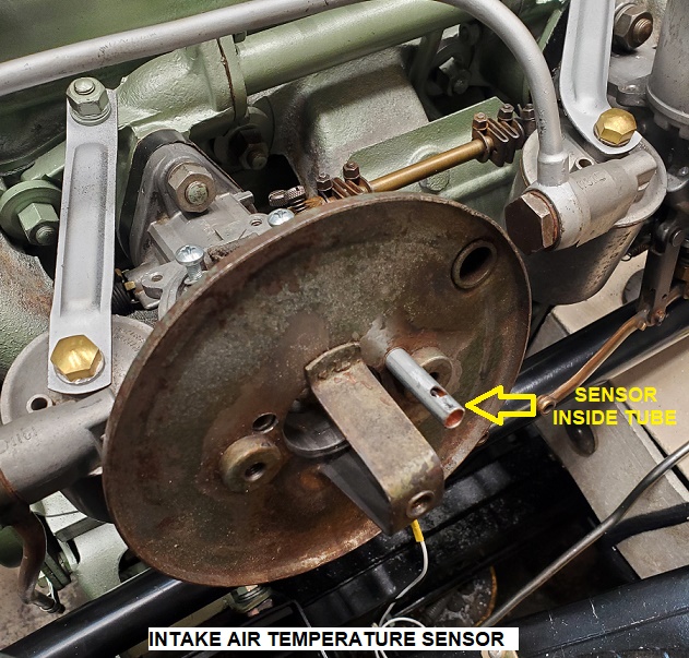
The wires for the thermistor pass down through what was originally the hole for the piston lift pin.
COOLANT TEMPERATURE SENSOR
Another input required by the ECU is the engine coolant temperature. I achieved this by installing a coolant temperature sensor through a replacement for the triangular water gallery cover fitted to the 100 engine adjacent to the water pump.
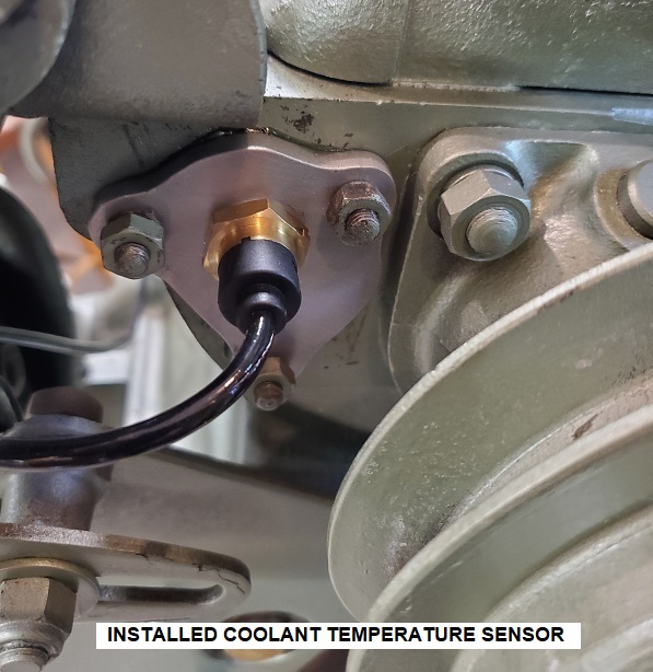
Fortunately, I have my BN1 close by and am able to check sight lines to ensure that none of these modifications can be easily seen.
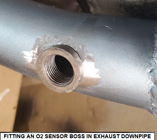
OXYGEN SENSOR
The (ECU) uses a lambda (O2) sensor to measure the oxygen content of the exhaust gases leaving the engine. I originally installed this sensor in the exhaust downpipe quite close to the manifold flange however, after some more research, I discovered that the sensor should be installed at least 80 cm from the exhaust valves so was obliged to remove the threaded boss that I had so carefully welded into my original curvature downpipe, weld up the hole, and reinstall the boss down near where the flex pipe is attached.
The signal from the O2 sensor has to be sent to a transceiver which generates a different type of signal for the ECU to use. This transceiver also drives a gauge which shows the air/fuel ratio being delivered to the engine by the injectors. I have mounted the gauge on a hinge so that it can be folded up behind the dash and hidden from view.
THROTTLE POSITION SENSOR
The ECU uses information from the MAP sensor and a throttle position sensor (TPS) to determine the amount of air entering the engine. Finding a suitable position for the TPS proved to be a significant challenge. The TPS is a variable resistor which is normally mounted on one end of the throttle butterfly shaft of the throttle body. For my system the carburettor bodies were effectively the throttle bodies and mounting a TPS on the end of the throttle butterfly shaft would place it in plain sight, something I am determined to avoid. In New Zealand Andy managed to build a linkage and mount the TPS inside one of the SU float chambers however he mentioned that it was quite difficult to get this to work reliably, and reliability was something else that I was determined to achieve. After much measurement and experimentation, I decided that the best location was at the throttle linkage pivot point high up on the driver’s footwell above the bellhousing. Originally this is a stainless-steel stud bolted through the footwell with a BSF nut on the inside.
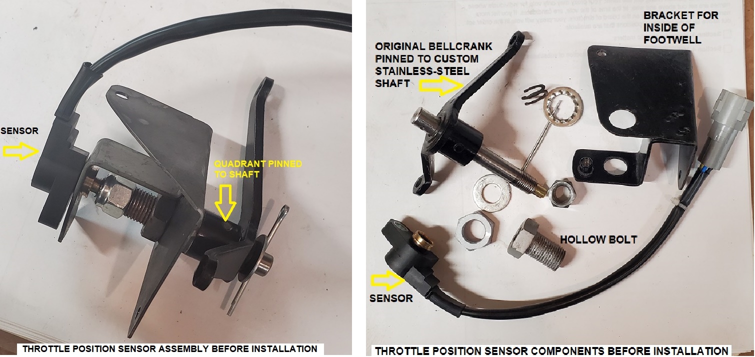
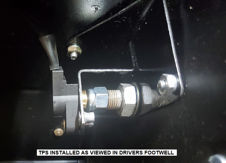
I built the parts with the aid of CAD (Cardboard Aided Design) and within a couple of days had a working system that I was very happy with which even incorporates a slotted hole that can be used to set the working range of the TPS.
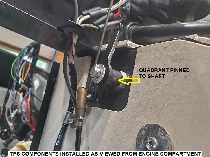
THROTTLE POSITION SENSOR (UPDATE)
Once I had all the electronics hooked up I was able to check the operation of the TPS and quickly discovered that the above system would not do the job. It turns out that to produce an adequate output signal the TPS has to rotate through close to 90 degrees and what I had done was only producing about 11 degrees of rotation. Back to the drawing board as they say. The problem was to convert that 11 degrees of rotation into something approaching 90 degrees.
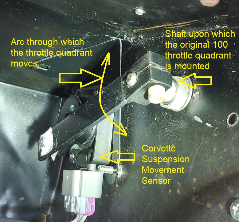
The Mk 2 version of the TPS uses an arm mounted on the throttle quadrant shaft to rotate a Corvette suspension movement sensor.
FUEL INJECTORS
The last link in the EFI fuel delivery system is the fuel injectors themselves. Andy had developed a brilliant piece of engineering that allowed him to mount injectors inside his H4 SU carburettors and was kind enough to send me the CAD, computer aided design in this case, drawings to allow me to have the parts 3D printed.
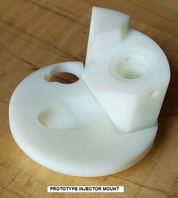
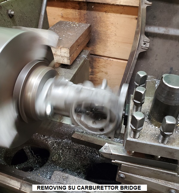
Being a bit of an originality freak I was somewhat reluctant to start hacking up a pair of 70-year-old carburettors to enable the installation of the injectors but, with the knowledge that there are hundreds of discarded H4 carburettors around the world as a result of so many 100’s being converted to using H6’s, I started by boring the throat of the carburettors to remove the original “bridge”. Then, utilizing tools of mass destruction, I removed the necessary material to allow the 3D printed nylon injector holders to be fitted snugly inside the carburettor body.
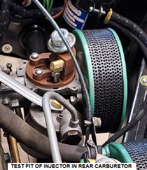
One of the things that Andy discovered whilst developing the EFI system for his BN4 was that pulsations from the fuel pump interfered with the fuel delivery. After much experimentation he fitted Honda pulsation dampers on the injector holders to resolve the issue. I have done the same.
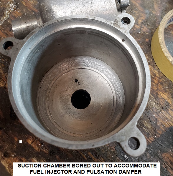
In order to fit all this modern technology under the original suction chambers I had to bore them out. Fortunately, the original castings are fairly thick.
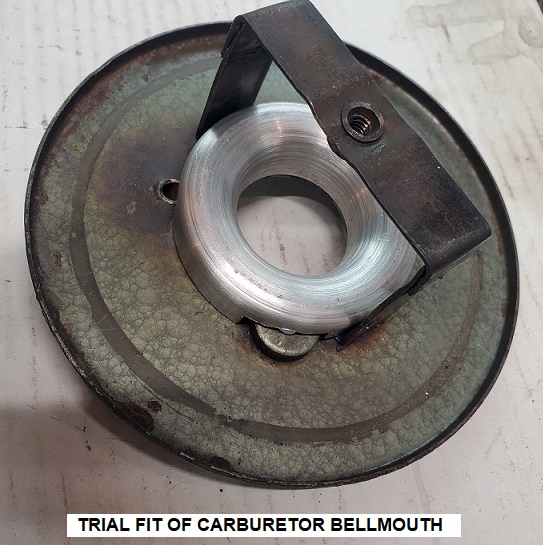
I have a very good friend who constantly strives to get absolutely as much power out of his race mini engine as possible and as part of his work has been able to confirm that a bell mouth fitted to the entrance of an SU carburettor makes a significant difference to the volume of air that will flow through it so I have machined up a pair to fit tidily inside the original air filters.
In order to make it difficult to see and protect it from engine compartment temperatures I have installed the Link ECU on the firewall inside the car near the wiper motor. Fortunately, this complicated and expensive piece of kit is an electrical “island” meaning that the case is not part of the grounding circuit allowing me to keep this car’s electrical system +ve ground, as original.
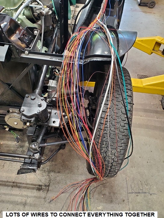
There are 42 wires in the ECU harness and identifying and connecting the 25 or so that I require took some careful work and help as I am partially colour blind and all the wires are identified by colour. Additionally electrical interference from the ignition system can cause serious problems with these types of electronics so care has been taken to route things onto the left side of the engine away from the distributor and coil as much as possible. I will also be fitting suppressor type spark plug wires to help with this.
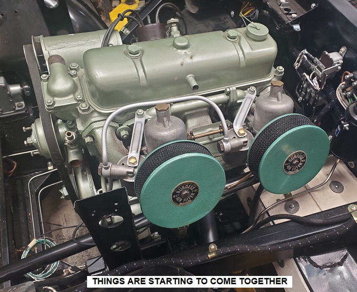
I ran out of green hammertone for the air filter gauzes … 🙁
That is all for now …. Hopefully I’ll get this all working during the summer of 2025.
Hi Michael,
Your post is very interesting. I m finishing the restauration from a BN2 and think about EFI for it.
What about the project now in May 2025 ?
Have you been able to finish it?
Thank you for your feedback
Regards
Michel
Hi Michel, somehow I missed your question my apologies. I managed to get the engine running fairly well although of course some fine tuning will be required. I actually drove it a couple of miles down our country road and it performed very well. Since then I had to put the project to one side while we had an addition put onto our house above the garage, a process which took much of 2025. I don’t do paintwork so I sent the car off for painting with the promise that it would be finished early in the fall so I could work on the final assembly. Well it is now the end of January 2026 and the car still isn’t back from paint.
Maybe this summer.