
I had a panic call from Judy a couple of days ago … her Maxima had stopped on the side of the road … HELP!!
Apparently, the battery and brake warning lights had been coming on intermittently for a while and now the battery was dead.
 Unfortunately, the Maxima is too wide for the Carcamel so it was into town for a new battery as this 2014 Nissan still had its original battery. After installing the new battery, the warning lights stayed on for a while but then went out. Just to be sure that all was well I did a voltage check on the battery and when the engine was running the voltage rose about 1.5 volts so all was well … NOT!!
Next time she went out in the car the 2 warning lights came back on and stayed on. A second voltage check indicated that there was no voltage rise with the engine running … not a good sign.
I did all the normal tests, checked the cables, engine grounds, serpentine belt etc., etc. but the alternator refused to produce the goods.
A quick OBDII scan showed no fault codes so everything pointed to a faulty alternator.
The alternator on this 3.5 liter V6 is so far buried on the front of the engine it is almost impossible to actually even see!

A check of the factory Workshop Manual was not encouraging.
REMOVAL
- Remove hoodledge covers (RH and LH).
- Remove cooling fan assembly. Refer to CO-16, “Removal and Installation”.
- Remove the A/C compressor. Refer to HA-34, “Removal and Installation for Compressor”.
- Remove A/C idler pulley EM-15, “Removal and Installation of Drive Belt Auto-tensioner”.
- Disconnect the oil pressure switch EM-36, “Exploded View”.
- Disconnect the generator harness connectors.
- Remove the generator bolt and nuts, using power tools.
- Remove generator bracket.
-
Slide the generator out and remove.
A small item like “Remove cooling fan assembly” was actually a very major undertaking and consisted of:
REMOVAL
- Drain coolant from radiator. Refer to CO-11, “Changing Engine Coolant”.
- Remove hoodledge covers (RH and LH).
- Remove front bumper fascia. Refer to EXT-16, “Removal and Installation”.
- Remove battery tray. Refer to PG-68, “Removal and Installation (Battery Tray)”.
- Disconnect reservoir hose.
- Disconnect radiator hose (upper) and radiator hose (lower).
- Remove A/C condenser. Refer to HA-42, “CONDENSER : Removal and Installation”.
-
Disconnect the CVT oil cooler hose
This was looking VERY serious and call to the dealer produced a “rough estimate” of $1500.
Well, I can think of a lot of things that I would much prefer to spend $1500 ++ on so decided that I had best put my MGBGT to one side and see what this was all about.
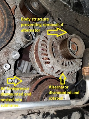
After disconnecting the battery and removing the various shields and covers it seemed to me that the alternator may just fit out the gap above the AC compressor and the below the frame.

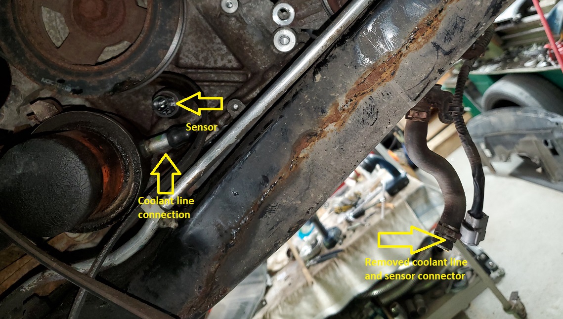
 I removed the serpentine belt and the belt idler then took out the 4 bolts securing the AC compressor. Next, I removed a cable from what I believe is the oil pressure sensor next to the oil filter and the coolant line going to the oil filter housing and plugged the lines for that.
 Next, I removed the long bolt at the bottom of the alternator and the one at the top which allowed access to the electrical connections on the alternator after removing the top radiator hose and intake trunk.

 Unfortunately, the hole through which I had hoped to extract the alternator was about 4 cm too small.
 After a bit of head scratching and another long look at the radiator I decided that there was a better way to get this alternator out.
The entire engine, transmission and suspension are in a subframe which is secured to the body with 4 bolts through rubber mounts. It is quite apparent that during assembly this entire subframe is introduced to the body from the bottom. I figured that if I could lower the front of this subframe 4 or 5 cm I could extract the alternator.
 The bolts securing the subframe are very long and take 48 turns to tighten. By supporting the subframe then unscrewing those bolts in 10 turn increments I discovered that at 40 turns down there was sufficient space to extract the alternator after bending a push retainer tab out of the way.

 Once I had the alternator out and on my workbench the problems were pretty obvious. The case was cracked and it was very noisy when rotated.
New alternator on order. Hopefully reassembly it the reverse of reassembly.
Write A Comment