
BUILDING A “100R” ENGINE
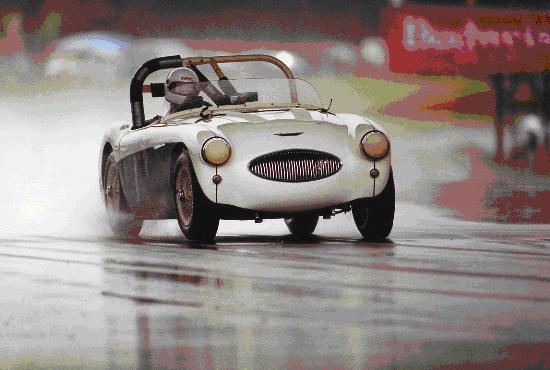
When I bought AHS3903 it was always my intention to race it for at least a couple of seasons and, some 6 years after the purchase, I managed to get the car finished just in time for the 1990 Austin Healey Challenge.
Some years earlier I had had the opportunity to drive John Chatham’s rally prepared 100 the engine of which was based on the block of a London Taxi diesel engine. The car was very impressive with lots of power and a very wide torque band.
I decided that rather than risk damaging AHS3903’s irreplaceable original block I would build up a special competition engine if I was going to use the car in future events. The specs that I laid down for the engine were these:
1. Taxi crank with a 4” stroke (rather than the original 4.375”)
2. Lightweight forged pistons
3. Carrillo connecting rods
4. Big valves and gas flowed 100S head
5. Cam with 300 degree duration and 0.500” valve lift
6. Lightweight flywheel
7. Crank triggered electronic ignition
8. 2 x 45DCOE Weber carburetors
9. Adjustable cam timing
10. 10.5 / 1 compression
11. Strapped center main bearing
12. Gear reduction starter
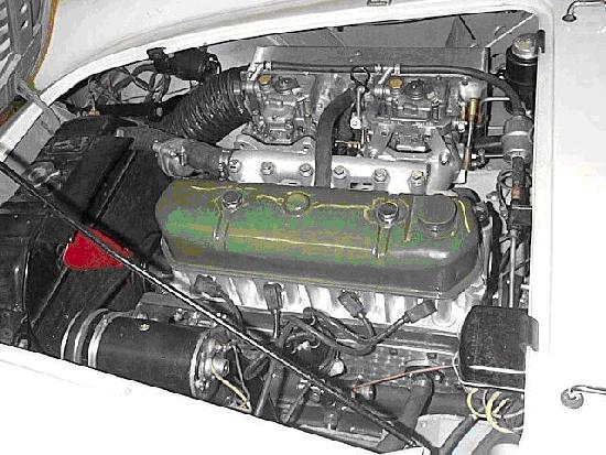
I figured, in blissful ignorance, that an engine with these specs should wind up to 7000 r.p.m. and develop over 200 BHP. I was lucky enough to have a spare head, exhaust manifold, and a “one off” intake manifold for the Webers which have different mounting stud configurations than the DCO3 Webers available from the factory as an option for the 100S. I could modify a standard 100 block and I managed to buy 2 NOS FX3 taxi crankshafts, with bearings on EBay!!
Other items such as the modified rocker cover, flat plate tappet cover, special distributor and tachometer drive, and enlarged oil pan were relatively easily copied from the ones in the original engine.
I was prompted into finishing the engine when I decided to take AHS3903 into the 2002 Targa Newfoundland but the rules for the Targa necessitated the elimination of the crank triggered ignition.
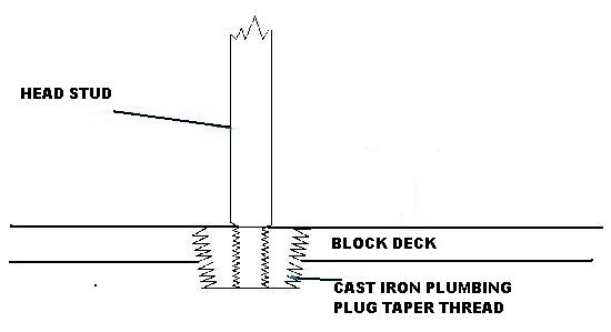
When time came to do the necessary machining and assemble all the parts I was simply too busy to take it on, so I sent the whole lot down to Barry Sale of PHP Racengines in Chicago and asked him to see what he could achieve. The biggest issue was repositioning the head studs in a standard 100 block to take the 100S head. The problem is that inside a block the manufacturer casts special bosses which are drilled and tapped to accommodate the head studs. In cross section the deck looks like this.

Of course if you decide that you have to move the studs there are no bosses in the new positions so you end up with either very shallow threads, or worse yet, trying to cut a thread where one side is into a boss and the other is not. In addition to this head stud issue Barry encountered a problem with fitting the Diesel crank into the 100 block. The problem was that the thrust faces on the center main bearing of the taxi crank were closer together than they are on a standard 100 crank. This required some fairly unusual machining of the block and the narrowing of the center main bearing shells.

The other problems were not too difficult to resolve. The taxi crank has 6 flywheel mounting bolts so I had an aluminium flywheel made with the appropriate mounting holes and the ring gear installed to it with the “lead in” of the teeth on the front side to accommodate the reduction gear starter.
I decided to stick with an original 100S type exhaust manifold after reading of the problems that the factory team had encountered at Sebring when their tube type headers broke up during the race.
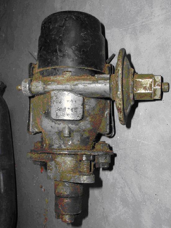
One other “issue” that I encountered was coming up with a suitable distributor. On the 100S engine the distributor was moved to the opposite side of the engine so that it was not under the repositioned manifolds. This move resulted in the need for a distributor which rotated in the opposite direction and I managed to get one from a 1954 Humber Hawk which fit the bill perfectly.
We consulted Dema Elgin of Elgin Cams and he recommended, and supplied, a milder cam than I had envisioned with a 274 degree duration and lift at the cam of 0.295” (0.486” valve). The rocker ratio on the 100S head is 1.65/1

I have to give Barry credit; once he got started he managed to make things work and to get the engine assembled and running in very short order for me to take it back to Toronto and install it before the 2002 Targa Newfoundland.
In Newfoundland the engine performed flawlessly until we encountered a Volvo P1800 strategically positioned across the road which ended the rally for us. After that event I, in my infinite wisdom, decided I could get more power out of the engine with a wilder cam and some careful “manipulation” of the specs. The first thing I did was measure everything carefully to determine where things stood. I found that the compression ratio was only 9.22/1 and that the variation in the combustion chamber capacities was far greater than was desirable. After pulling out a couple of the studs while torquing down the head I decided that this had to be solved once and for all.
I mounted the block in mill and bored out all the troublesome head stud threads and installed cast iron taper thread plugs. I then milled these flat and then tapped and drilled them for the studs.
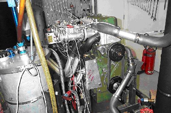
I ordered up a 300 degree cam with slightly more lift, took an additional 0.050” off the head to bring the compression ratio closer to 10.5/1 and balanced the combustion chamber volumes. After careful reassembly I hauled the engine back to Chicago to have Barry test it again on his dynamometer. We performed 22 runs on the dynamometer while Barry fine tuned the carburetors and adjusted the cam and ignition timing to get the best he could out of my improvements, The result was an increase of only 9 BHP to 175 at a higher r.p.m. but no improvement in torque and it was only after mulling this rather disappointing result for some time and reading a lot more about engine development that I realized that it was going to be very unlikely that I would ever get much more power from this engine configuration and here is why.
To develop power an engine has to ingest a gulp of air (which contains a bit of fuel). The force to get this air into the combustion chamber comes from the good old 15 p.s.i. (pounds per square inch) of atmospheric pressure. What the atmosphere has to do, when the inlet valve opens, is accelerate a slug of air through the port, past the valve and into the cylinder. The problem is that although that slug of air doesn’t weigh that much 15 p.s.i isn’t that much of a force. The laws of physics determine that the rate of acceleration is proportional to the inverse of the mass being accelerated and the force accelerating it. In simple terms the old atmospheric pressure can only push so much air down that port in a given amount of time. At 6000 r.p.m. the piston moves from the top, essentially where this process begins, to the bottom, where it ends in 1/100th of a second. That isn’t that long. Now there are a bunch of “mitigating circumstances” but when you get right down to it that is what has to happen. Things can be improved a bit by making the valves open longer and further, or cleaning out the ports and fitting bigger carburetor throats but the fact remains that 10,000 r.p.m. just wasn’t going to happen on a long stroke 2500c.c engine. This concept is summarized in the old adage that it is very hard to exceed 3000 – 3500 ft/min mean piston speed and with its 4” stroke the “100R” engine is doing 3333 ft/min at 5000 r.p.m. Of course F1 engines were getting upwards of 5500 ft/min in the early 90’s but that’s a very different story.
Michael, I like the sound of your engine. I am in the UK, would you build one for me like this? I have a 1953 BN1. Would you recommend a 4 or 3 speed box with this and which diff did you run with?
You mention fitting a crank triggered ignition, then discuss a distributor on the opposite side. What about the crank triggered ignition? How was that done?
Hello Richard,
thanks for the reply, you are obviously a pioneer like john Chatham. Interesting that the JE pistons were not up to the job. Based on your experience, I’d like to follow your design, if that’s OK. Can you tell me the dimension/details of the Saenz rods for the Camry pistons?
thanks and regards,
Paul.
Hello Michael, this is a very interesting engine project. Using the Taxi crank with a shorter stroke would mean longer con rods, I beleive. I see you used Carrillo rods. Were these standard catalogue items or did they have to be custom made?
thanks for your help,
Paul.
Hi Paul, Yes in the first version of the engine I used custom made Carrillo Rods and J. E Pistons but unfortunately the pistons were not well designed and we found that the land between the 1st and 2nd ring had collapsed when we were freshening the engine up the first time.
After that I had another set of rods made, this time by Saenz, which allowed me to use Toyota Camry pistons. The overall cost of that package was far less than the Carrillo rods alone and has proven to be a very reliable arrangement.
Unfortunately Ken, as far as Targa Newfoundland is concerned, as you mused, The Rules are the problem . Superchargers must be OES (Original Equipment Specification) for our class and adding a supercharger multiplies your capacity by 1.7.
On the other hand a normally aspirated push rod engine has an advantage in that its capacity is multiplied by 0.8 so our 2.5 engine becomes a 2.0 which puts us in the small capacity class.
In addition to this Geoffrey Healey’s accounts of the record breaking attempts contain regular references to all sorts of “blown up” engines and a reliable engine is essential for long distance events like Targa. I just don’t feel that I have the skills and equipment to produce a reliable supercharged engine. That is a very complex undertaking.
So your modifications weren’t really of a new technology that wasn’t available to the Healey team in 1955, right? They decided to supercharge for Bonneville. It seems the only logical path if your bottem end is strong enough. Forged crank’s are available for 100’s now, I think. Is supercharging legal for the Targa? Maybe the Bonneville car homolgation of one is enough?