
I am currently restoring a very low mileage and virtually rust free 1956 Austin Healey 100 BN2.
Having this chance to disassemble such an original car has presented me with a unique opportunity to study construction details which, at least in this part of the world, are usually lost to the ravages of rust.
For anyone undertaking an accurate restoration of a Big Healey these details may be of interest.
Rear Fender Attachment
Details about the types of fasteners used and their positioning, particularly in the “dogleg” area, are very difficult to determine from a rusted mess which has usually been previously repaired, often more than once. Fortunately, the car I’m working on has never been apart and has only heavy surface rust and all the original steel and fasteners are exactly as they were when the body shell was built at Jensen Motors 67 years ago.
Each rear fender was secured with the following fasteners:
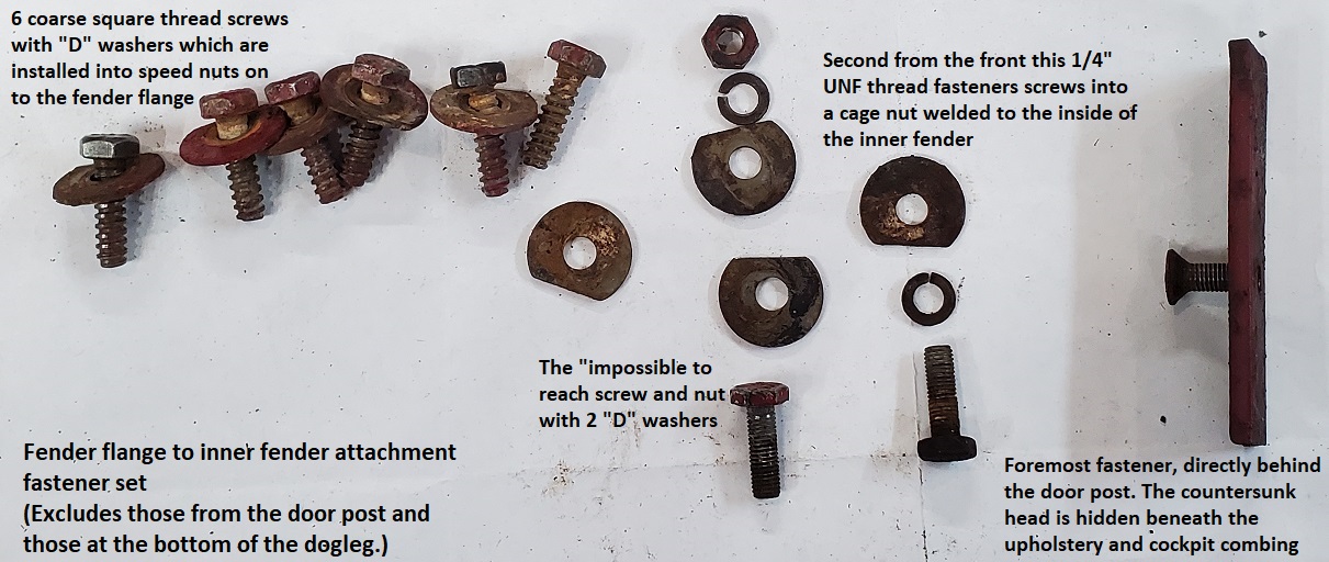 Five square thread, hex head screws with “D” washers were inserted from inside the trunk (boot) into “speed nuts”. The “speed nuts” were clipped to the fender (wing) flange. Interestingly there were actually two different head types on these hex head screws. Some had a small raised flange and others did not.

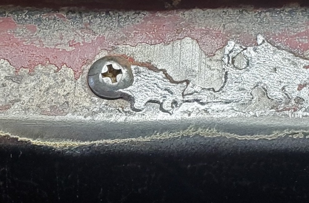
One countersink flat head Phillips 1/4″ x 3/4′ UNF screw was inserted from inside the cockpit into a rectangular plate 1/4″ thick located directly rearward of the rear door post. The countersink head is used because the aluminium cockpit combings are installed over this screw.
One ¾” x ¼” UNF hex screw into a ¼” UNF cage nut.
Eight countersink flat head Phillips 10/32 x ½” screws with split washers and hex nuts were used to secure the fender to the rear door post. (Not pictured.)
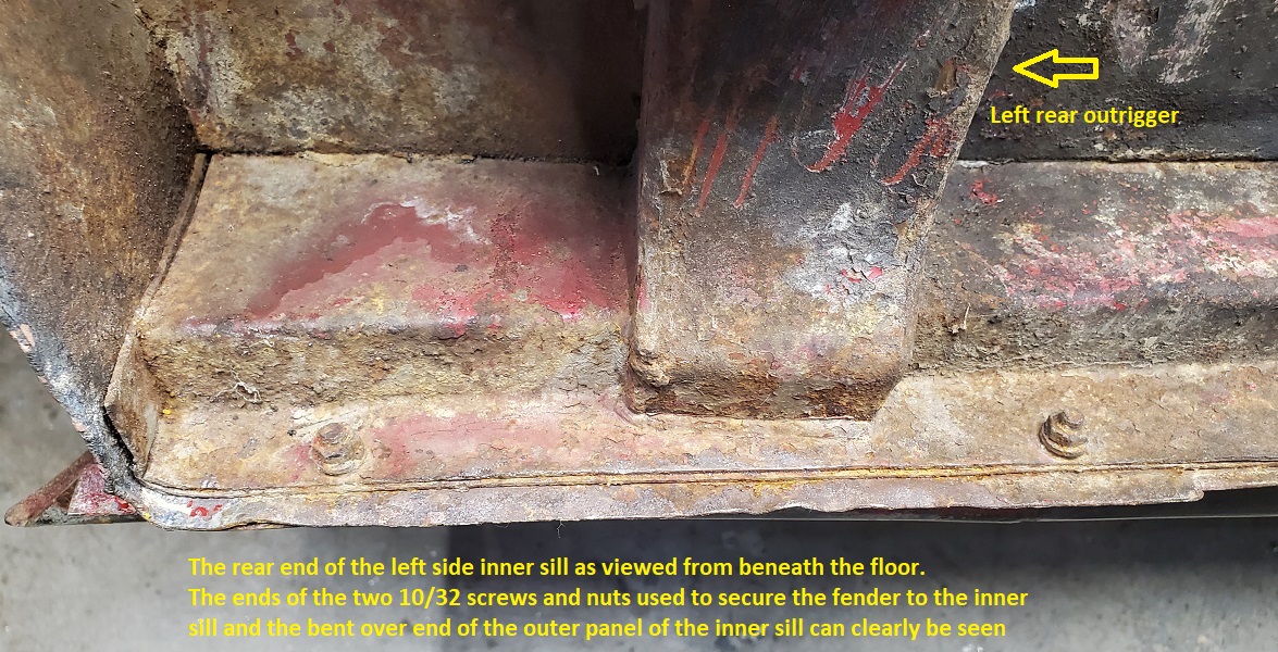
Two 10/32 x ¾” long oval head Phillips screws with flat washers, split washers and nuts secured the lower flange of the fender to the flange of the inner sill.

One ¾” x ¼” UNF hex screw with 2 “D” washers one split washer and a ¼” UNF hex nut.


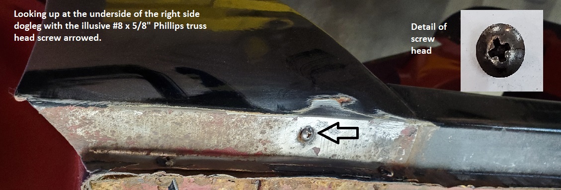
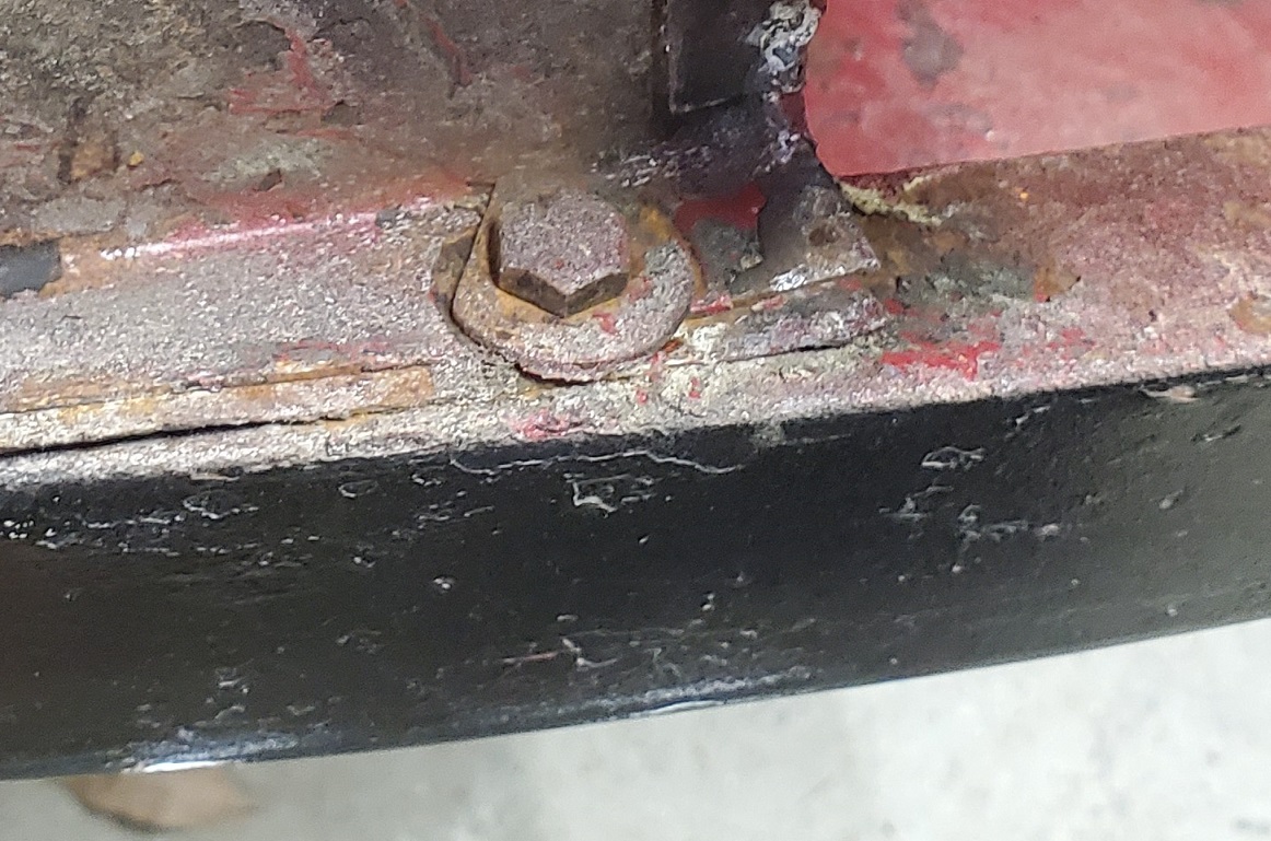
One #8 x 5/8” truss head screw vertically through the fender and into the outer sill extension. It is thought that this self tapping screw was inserted during body assembly to maintain the door to fender gap as the rest of the fasteners were added. It is quite apparent that body lead was used to “tidy up” things in this area.
One square thread, hex head screws with a “D” washer inserted through the edge flange of the trunk floor into a “speed nut” which was also clipped to the fender (wing) flange.
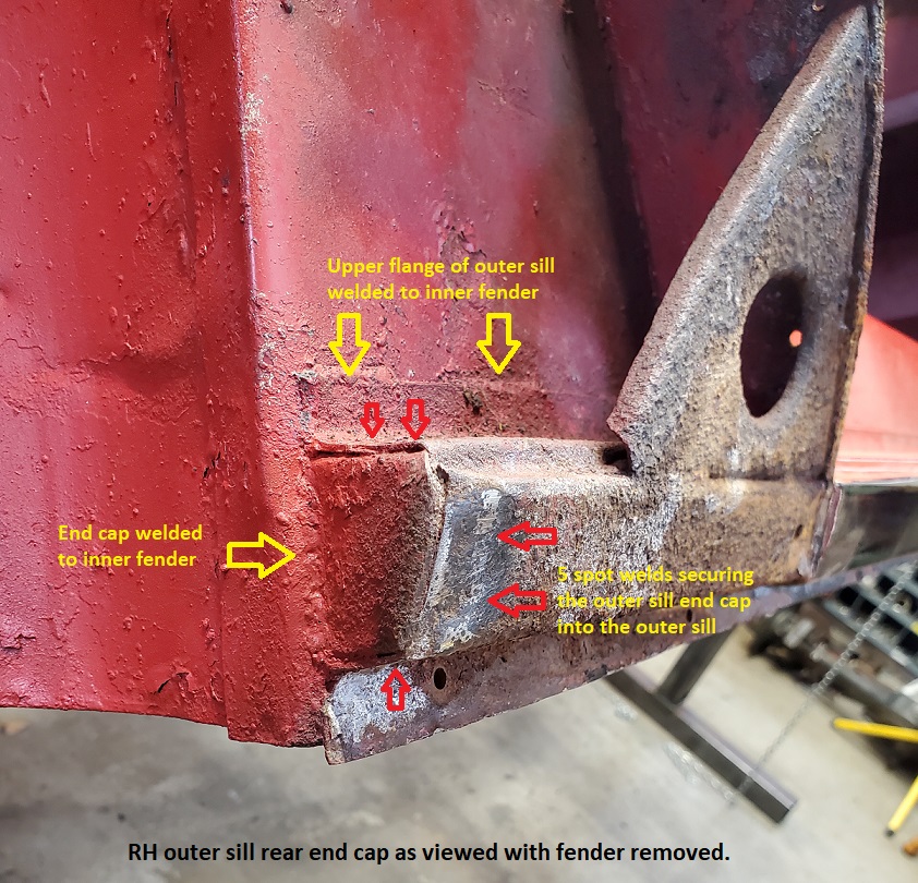
Inner Sill and Dogleg Construction.
It is interesting to note how the end of the outer panel of the inner sill is bent over to close off the rear end of the inner sill assembly.
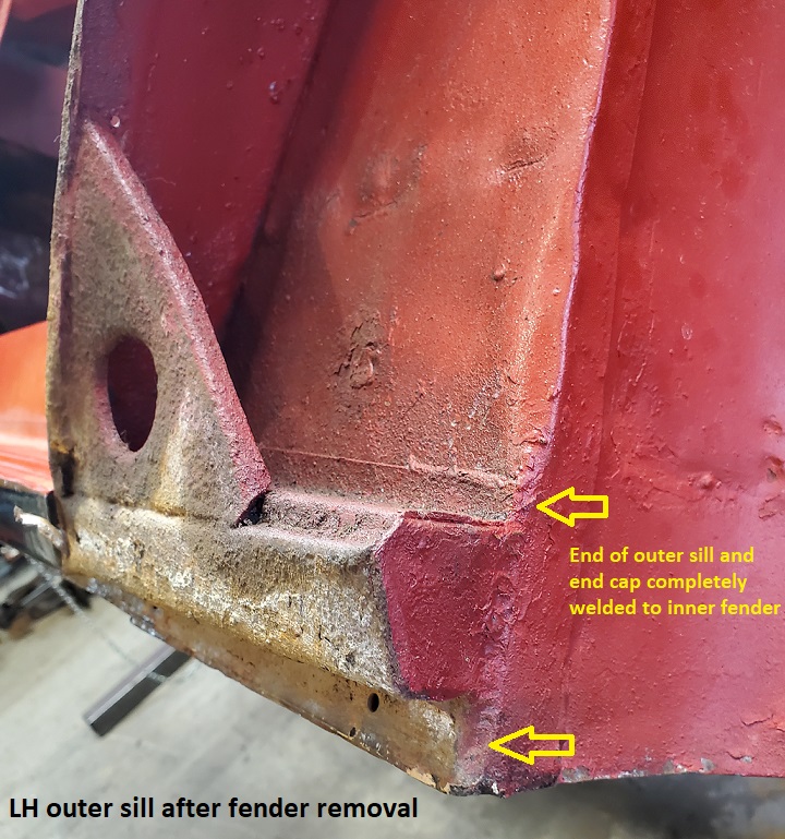
The end of the outer sill was clearly welded securely to the inner fender and the triangular gusset was welded to the outer sill in 2 places and to the rear door post in one.
Remarkably original construction.